WELCOME TO THE OFFICIAL WEBSITE OF BETTEN TENSIOMETER!
ADDRESS:Betten technology Co.,Ltd.22nd Floor,Ocean Blue Diamond,No. 501 Nandi West Road,Heping District,Shenyang,China
PHONE:+86-13911001672
TEL:+86-24-24754482
BDR Rope Tension Tester User Manual
Summary:
1.1 Main usage and application
Rope Tension Testing Instrument can be applied to various occasions, such as power industry, telecommunications industry, transportation industry, glass curtain wall decoration, cable way industry, construction industry, pleasure grounds, tunnel construction, fishing, major research institutions and teaching institutions, testing institutions and other occasions involved with the tension of ropes and steel wire ropes.
1.2 Product characteristics
It has the rope structure with tension force, and can directly measure without disassembly.
It has the light weight, simple structure, convenient operation, and applies to any situations.
It has the stable performance, high measurement accuracy, with automatic system compensation function.When the specification of the tested rope the same as the rope tension testing instrument rope number, the measurement accuracy can reach 3% error or less within the rated measurement range.
It has broader range of measurement, with 19 kinds of rope diameter measuring functions.
Applied range:applied to flexible, stretched ropes,such as various steel wire ropes, high-strength ropes etc.
Accuracy grade: 3~6% of maximum function (depending on the rope form and features).
Rope Diameter: ¢6~¢40mm.
1.3 Specifications and model
Model | BDR-20 | |||||||
Number | 1 | 2 | 3 | 4 | 5 | 6 | 7 | 8 |
Diameter | Φ6 | Φ8 | Φ9 | Φ10 | Φ12 | Φ14 | Φ16 | Φ18 |
Load division value(KN) | 0.01 | |||||||
Output connector | Rs232 9-hole socket | |||||||
Power | Rechargeable battery charger (charging voltage 100V~240V) | |||||||
Working temperature | 5℃~35℃ | |||||||
Transport temperature | -10℃~60℃ | |||||||
Relative humidity | 15%~80%RH | |||||||
Working environment | No vibration focus and corrosive media around | |||||||
Net weight | 4.7kg | |||||||
Dimension | 650×375×100(mm) | |||||||
Model | BDR-50 | |||||||
Number | 1 | 2 | 3 | 4 | 5 | 6 | 7 | 8 |
Diameter | Φ12 | Φ14 | Φ16 | Φ18 | Φ20 | Φ22 | Φ24 | Φ26 |
Load division value(KN) | 0.01 | |||||||
Output connector | Rs232 9-hole socket | |||||||
Power | Rechargeable battery charger (charging voltage 100V~240V) | |||||||
Working temperature | 5℃~35℃ | |||||||
Transport temperature | -10℃~60℃ | |||||||
Relative humidity | 15%~80%RH | |||||||
Working environment | No vibration focus and corrosive media around | |||||||
Net weight | 4.7kg | |||||||
Dimension | 650×375×100(mm) | |||||||
Model | BDR-100 | |||||||
Number | 1 | 2 | 3 | 4 | 5 | 6 | 7 | 8 |
Diameter | Φ20 | Φ22 | Φ24 | Φ26 | Φ28 | Φ30 | Φ32 | Φ34 |
Load division value(KN) | 0.1 | |||||||
Output connector | Rs232 9-hole socket | |||||||
Power | Rechargeable battery charger (charging voltage 100V~240V) | |||||||
Working temperature | 5℃~35℃ | |||||||
Transport temperature | -10℃~60℃ | |||||||
Relative humidity | 15%~80%RH | |||||||
Working environment | No vibration focus and corrosive media around | |||||||
Net weight | 7kg | |||||||
Dimension | 650×375×100(mm) | |||||||
Model | BDR-200 | |||||||
Number | 1 | 2 | 3 | 4 | 5 | 6 | 7 | 8 |
Diameter | Φ26 | Φ28 | Φ30 | Φ32 | Φ34 | Φ36 | Φ38 | Φ40 |
Load division value(KN) | 0.1 | |||||||
Output connector | Rs232 9-hole socket | |||||||
Power | Rechargeable battery charger (charging voltage 100V~240V) | |||||||
Working temperature | 5℃~35℃ | |||||||
Transport temperature | -10℃~60℃ | |||||||
Relative humidity | 15%~80%RH | |||||||
Working environment | No vibration focus and corrosive media around | |||||||
Net weight | 7kg | |||||||
Dimension | 650×375×100(mm) | |||||||
1.4 The Working Principle
The determination of rope force is classified into two types: intrusive and non-intrusive. The so-called intrusive force test refers to that at the ends of or in the middle of the rope, after having it cut, attach it to a pull sensor, and read out the rope force directly, which is one of the most accurate and visualized method of measuring force, as is shown in the following diagram 1 and 2.

( Diagram 1)

( Diagram 2)
This force testing method requires large investment; only applies to pilot studies and a few projects that have huge tonnage and high requirements. It does not apply to pre-stressed structural projects with large amount of rope layout.
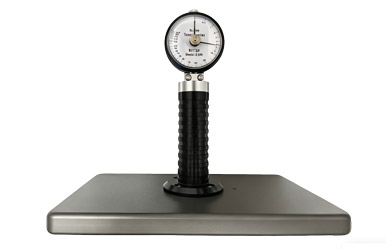
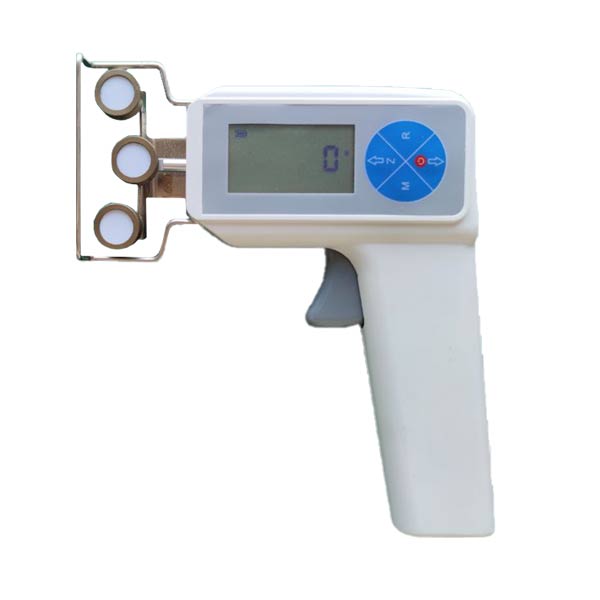
The non-intrusive force measuring method is also divided into two kinds, one is the vibration frequency measurement method, namely, there are function relations between the rope self-vibration period T and the rope inner tension H, between the rope length L and the rope quality W. Through the formula it can be known that if the rope vibration period T is measured, the rope inner tension H can be calculated. The principle is relatively simple, but in the process of transforming the vibration into signals, and then exporting rope pull value through computer processing, more instruments and equipment are required and it is more difficult for workers to grasp. Besides, it is inconvenient for high-altitude operations. In addition, the supporting conditions at the rope ends have influence on the vibration cycle, and also on the force measurement accuracy. Another principle of rope force measurement is based on principles of mechanics. As is shown in the following diagram, there are function relations between the horizontal displacement δ of rope force and the pull H, between the horizontal force P and the length of the rope. Under the condition that displacement keeps a certain values, the more the rope pull H, the greater the horizontal force P.

( Diagram 3)
Using force sensor output the horizontal force P, after the microprocessor treatment into force, liquid Crystal Display: The above principle is also relatively simple, but the relation between the horizontal force and the rope force, is still relevant to the rope diameter, the cross-section structure, the rope extending rate and the degree of the pull. We can obtain exact and stable rope force through amendments of the microprocessor and precise calibration and so forth. It has reached the level of similar foreign products through trial and testing.
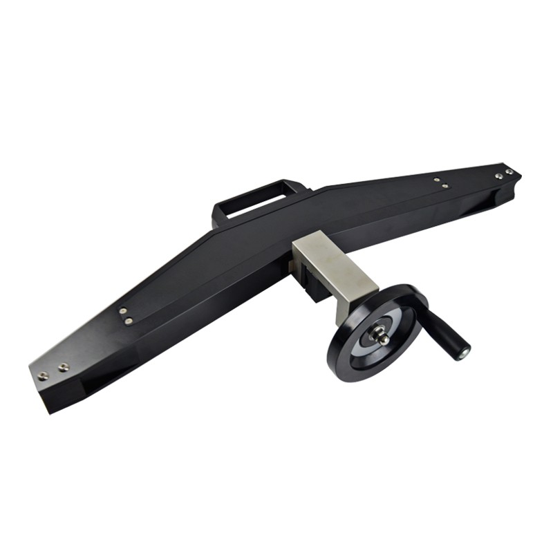
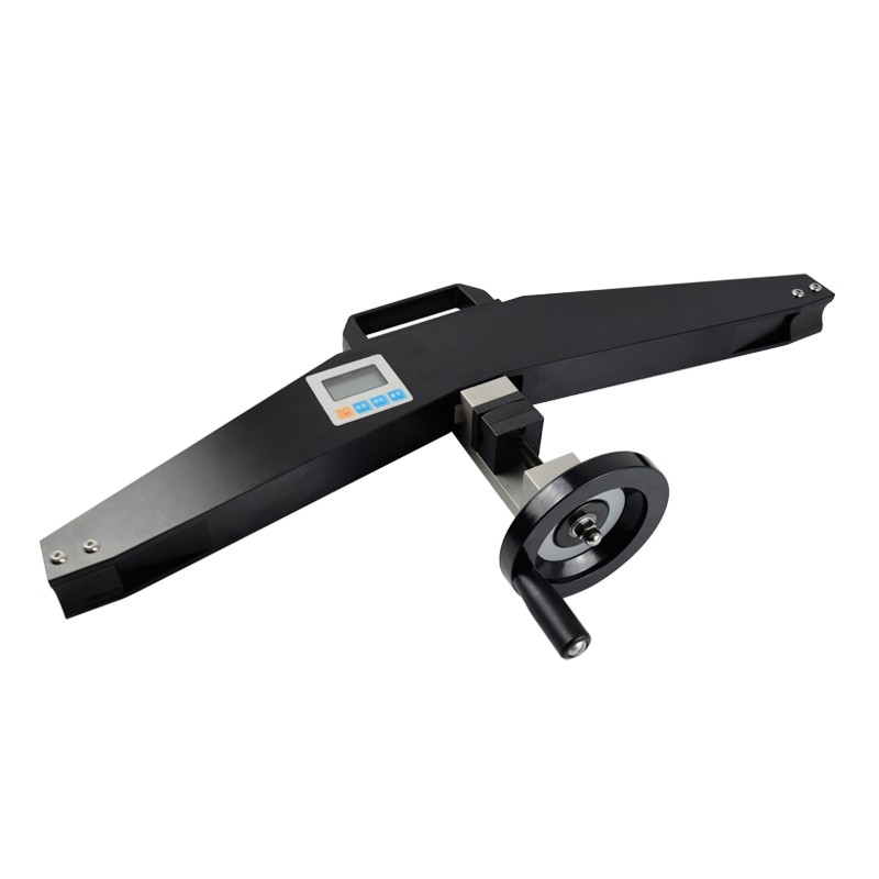
The product structure
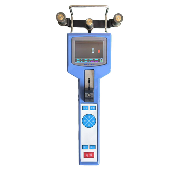
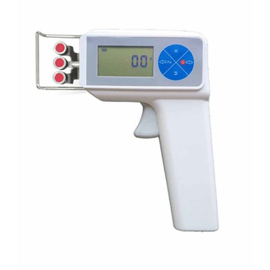
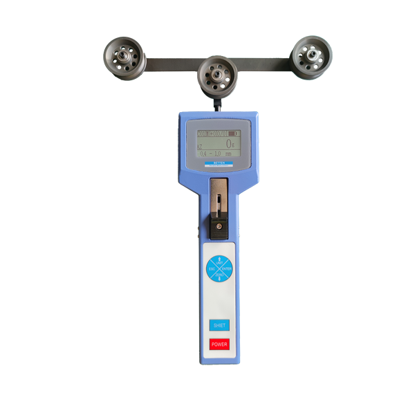
2.1 Outline structure

( Diagram 4)
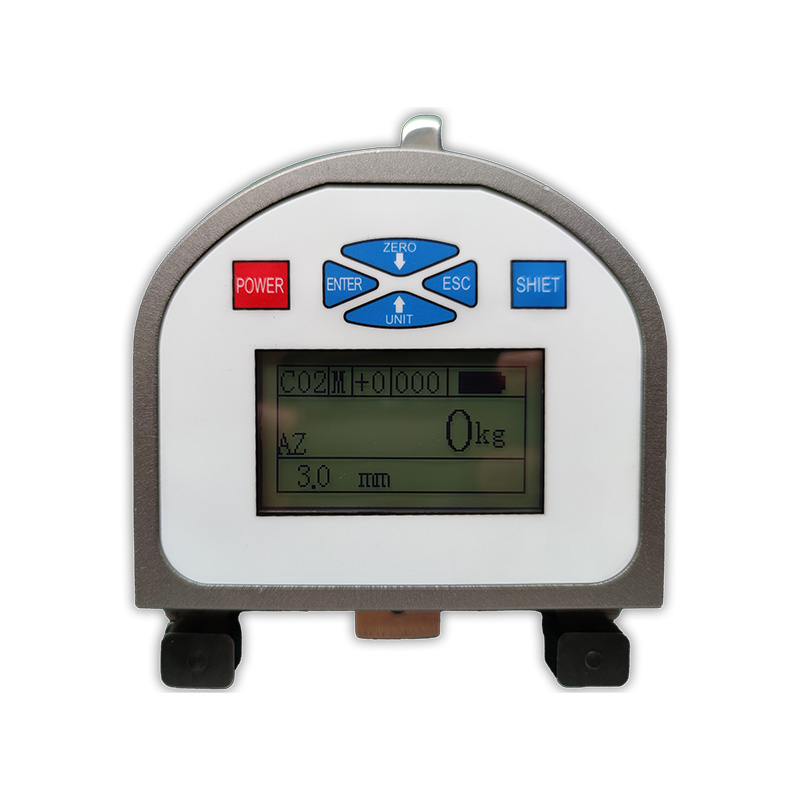
2.2 LCD screen function

( Diagram 5)
2.2.1 ON/FF:Press ON/FF ,the power turn on or off.
2.2.2 MODE: When in measuring interface ,press “MODE”key to enter into setting interface;when in setting interface, the “MODE” button can be used for saving.
2.2.3 MEMO:When in measuring interface,it can be used for data storage.
If the user save data before,when the user press “MEMO” button in measuring interface,the screen will display “MEM”, if not ,it will not disappear. Press “MEMO” key for 5 seconds,the stored data can be viewed. When in setting interface ,it can be used as” move up” function .
2.2.4 Zero:When in measuring interface,press “Zero” button to clear the data on the screen.
When in setting interface ,the button used as return.
USAGE AND OPERATION
3.1 Arrangement and check before using
3.1.1 Check the battery ,if not enough ,need to charge first.
3.2The operation and instruction in use
3.2.1 (UNIT)Unit setting:Turn on ,into measuring interface,Press“MODE”key into setting interface, press “ MODE” key again to enter into unit setting , press “MEMO” button to choose unit , choose the unit you need , press “MODE” key for saving and return to setting interface. Show as the picture 6 shows:

(diagram 6)
3.2.2(PEAK)PEAK setting:After last step,press “MEMO” button to choose “PEAK”,and then press “SET” to enter into PEAK setting , PRESS “MEMO” button in peak mode .No display on the screen (means real-time measuring mode) . Two mode alternative, choose the mode you need ,and then press “MODE” key for saving,show as the picture 7 below:

(diagram 7)
3.2.3 (HIDT)Upper limit value setting:Press “MODE” button to enter into upper limit value setting , press “MEMO”“ZERO” button respectively to adjust number, choose the number you need and then press “MODE” button for saving,show as the picture 8 show below:

(diagram 8)
3.2.4 (LODT)Lower limit value setting:Press “MODE” key to enter into lower limit value setting , press “MEMO”“ZERO” button respectively ,choose the number you need and then press “MODE” button for saving . Same as upper limit value setting shows.
3.2.5 (LOSET)Peak min. Storage value: In peak mode ,when the
peak value is less than peak min. storage value ,the peak can not be saved,when enter into “peak min. Storage value “ interface, press “MEMO”“ZERO” respectively, to adjust number,choose the value you need ,and then press “MODE” for saving.
3.2.6 (OFFT)Auto-shut down time setting:when in this setting program , press “MEMO” “ZERO” button to number adjustment , choose the number you need and then press”MEMO” for saving .It can setting auto shut down between 0 min to 9999 min., it can be also set“0000”for not auto shut down. If you choose not auto-shut down , after set "0000" and then press "MODE" to complete. In the meanwhile it turn back to setting item interface .The instrument default shut-down time is 30 minutes.
3.2.7 (BDR NO)Cable number selection:Turn on and enter into measuring interface,and press “MODE” button into setting interface ,and choose the cable number you need ,and press “MEMO” for saving ,the instrument auto-shut down. Restart if use it .Show as the picture 9 shows:

(diagram 9)
3.2.8 (G.SET) Gravity acceleration setting:The user can set the gravity acceleration value according to local area,the default value is 9.800.
3.2.9 (BACSET) Backlight function setting: Under this setting item,if choose “ (YES)” indicates the backlight function is on ,if you choose “ (NO)” indicates the backlight function is off ,after selection ,press “MODE” key for saving and back to setting item interface.
3.2.10 (RESET) Restore factory setting:Under this setting item ,press “MODE” button to back to factory setting ,the machine off . Re-start to use it .
Testing
4.1 According to the diameter of the wire rope to select the cable number
Cable number selection standard correspondence table

Special wire ropes can be calibrated according to customer’s requirements.
Note: In testing ,put the top point towards the positioned block,and press the tested wire rope on the compression block tightly.
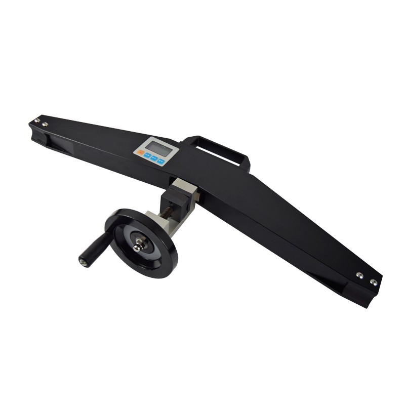
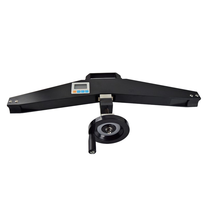
4.2 Loosen the locking handle , put the wire rope into the instrument(The pulley should be in full contact with the wire rope),tighten the locking handle so that the pulley seat move upwards to press the tested wire rope tightly,so that the wire rope can be full contact with compression block , Show as the picture 10. Enter into “PEAK” setting to choose measuring mode.
4.3Tighten the handle ,put the wire rope into the compression block tightly,the value show on the screen is the tension force .

(picture 10)
Maintain & Repair
5.1 Daily maintain,repair and calibration
5.1.1 Please use the matching charger for charging, otherwise, it will cause circuit failure, or even a fire.
5.1.2 Do not use the power supply beyond the rated voltage of the charger, or it may cause electric shock or fire.
5.1.3 Do not plug or unplug with wet hands, or it may cause an electric shock.。
5.1.4 Do not pull or drag the power wire to unplug the charger plug, in order to avoid the electric shock caused by breaking the wire.
5.1.5 Please use soft cloth to clean the instrument. Immerse the cloth into the water containing detergent, wring it dry and then clean up the dust and dirt.
5.1.6 Do not use volatile chemicals to clean the instru
5.2 Maintain and repair in use
5.2.1 Do not use this instrument beyond the maximum measurement range. Otherwise, it may lead to sensor damage, or even accidents.
5.2.2 When the test value exceeds the measurement range, the buzzer will ring continuously, and at this moment please remove the load quickly or reduce the load.
5.3 Maintain and repair in long-term stop in use
5.3.1 Please operate and stock the instrument under the prescribed temperature and humidity, or it may result in equipment failure.
Packing list
6.1 BDR-20, BDR-50 Packing list
User manual | 1 |
Check certificate | 1 |
Warranty card | 1 |
Certificate | 1 |
Software | 1 |
Charger | 1 |
Aluminum key | 1 |
RS232 Cable | 1 |
Tension Meter | 1 |
Hand wheel | 1 |
Cap nut and Flat key | 1 |
Aluminum box | 1 |
Dryer | 1 |
6.2 BDR-100, BDR-200 Packing list
User manual | 1 |
Check certificate | 1 |
Warranty card | 1 |
Certificate | 1 |
software | 1 |
charger | 1 |
Aluminum key | 1 |
Rs232 cable | 1 |
Tension meter | 1 |
Aluminum box | 1 |
Dryer | 1 |